Study on Partial Discharge Transmission Characteristics of Power Equipment Coil Insulation
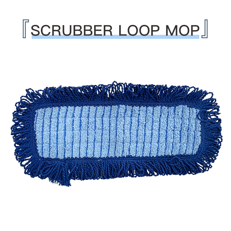
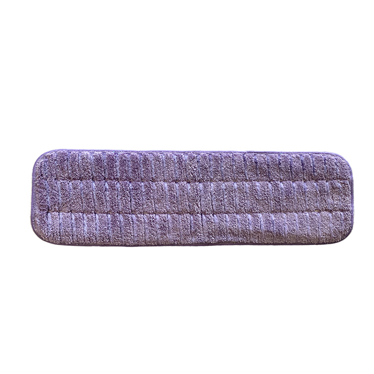
Study on Partial Discharge Transmission Characteristics of Power Equipment Coil Insulation Liu Shaoke 1 Zhang Kuikui 2(1. College of Mechatronics Engineering and Automation, National University of Defense Technology, Changsha 4100732, China;Hunan Communication Vocational and Technical College, Changsha 410004, China) The size, waveform and actual internal discharge It is very different from the waveform. In this paper, the partial discharge discharge characteristics of power equipment coils are studied, and the results of the research and experimental observations are obtained. The insulation of power equipment coils is the key to its ability to work properly. The initial partial defects of the coil, such as incomplete filling of the impregnated resin, cause gaps between the tantalum insulation and the slot insulation, causing partial discharge. Once the partial discharge occurs, it will cause chemical corrosion and local overheating, which will lead to further deterioration of the insulation, which will eventually lead to equipment failure. Therefore, partial discharge measurement is an important method for diagnosing the insulation condition of power equipment coils, and has gradually attracted widespread attention. Partial discharge typically manifests as a pulsed current that is transmitted along the coil conductor. Due to the complexity of the coil structure, the size and waveform of the partial discharge measured by the conventional method are often very different from the actual discharge size and waveform inside the insulation. By analyzing the partial discharge pulse current in the coil transmission, it helps people to understand the corresponding relationship between the partial discharge pulse current (apparent discharge current) of the external monitoring point and the internal discharge pulse current (actual discharge current) inside the insulation. And further locate the power supply point. In this paper, the partial discharge characteristics of coil insulation in power equipment are studied for the first time. The relevant research results are consistent with the experimental observations. 1 Coil insulation partial discharge circuit model When the partial discharge current is transmitted along the coil conductor, in addition to the conductor resistance, there are various distributed capacitances and distributed inductances. When considering distributed capacitance and distributed inductance, it can be represented by the L+C+K chain circuit shown. In the middle, G and C respectively represent the conductance and capacitance of the conductor to the ground (core), and R and L respectively represent the resistance and inductance of the conductor. It is a chain link that represents a coil. It can also represent a 当 when it ignores the change of each parameter. There are two kinds of coil insulation partial discharge forms in the L-C+K chain circuit, which are respectively the internal inter-turn discharge of the coil and the coil-to-ground (core) discharge. The results of the two discharge forms are similar, so we will analyze the second discharge form below. For the sake of generality, it is assumed that the latter half of the link is discharged to the ground, and is represented by the discharge current, as shown. The second half of the chain junction åŒ ground discharge occurs in the local area, so CiC2, it can be further simplified. It can be seen that the discharge current is transmitted in two paths in the coil branch: 1 and where is1 is directly transmitted to the branch via the coil branch 1: Liu Shaoke £19A3ca) e male iP Shi I associate professor research direction magnetic suspension control Mn motor control system and detection nghtsreserved, http:// above the formula is written as a matrix equation as follows: here = for the branch current coefficient matrix, For the capacitance matrix, it is the conductance matrix, which is a diagonal matrix. Similarly, we can list the branch voltage equation: = ten = diag is the resistance matrix, = diag is the inductance matrix, is a 1-effect frequency, f = 4 / Tmax when calculating, T is the analog partial discharge pulse rise time, lead The line inductance is generally 1 ~ 1.5H / m, here take L = PH, consider the motor insulation is new, so ignore the impact of G. The partial discharge pulse was simulated by the following double exponential pulse current. o(7) is very obvious for the discharge current pulse is at the actual position. Is Yin is1. Accurately solving the relationship between is and io involves solving the three-phase circuit network. This solution is very complicated. Considering that is2 is transmitted through the coil to the high-voltage terminal, its timing will be later than is1 (especially when the discharge point is close to the high-voltage end), and there is attenuation in the amplitude (especially when the neutral of the 3-phase coil is grounded). ), a reasonable approximation is to assume that is1=is2, and thus is1=is/2, so the above-mentioned related points are divided by 4 back, earth soil + see buckle 1: seven analysis is io conclusion is also suitable for is and Io. (turn down to page 7). Using the reduced order method, the equation (4) can be transformed into a state equation after =dt, and then solved by a numerical method. 3 Partial Discharge Transmission Simulation Calculation In order to understand the transmission characteristics of the partial discharge current in the coil, the actual motor stator coil was calculated using equation (4), and the calculation results were compared with the experimental observations. The simulation results of the motor åŒ ground discharge simulation show that the oscillating current is established in the coil branch even under the action of non-oscillating pulse current. The steeper the rising edge of the pulse (mainly depending on T2), the larger the oscillation amplitude and the higher the oscillation frequency. In the measurement of the actual PD pulse, it is found that at the measurement point of the lead line, the PD mostly appears as an exponentially decaying oscillation form, and its oscillation is rich in high frequency components, which indicates that the T2 of the actual PD is usually small. At the falling edge of the pulse, the oscillating current basically reaches a stable damped oscillation state, that is, the oscillating current oscillates with the source pulse current isl as an axis. The oscillation frequency component of the current is at the exit end of the coil is determined by the equivalent circuit, and the more the number of links (the larger N, that is, the farther the discharge point is from the exit end of the coil), the lower the oscillation frequency. The amplitude of the oscillating current component of the current io at the exit end of the coil may be larger than the amplitude of the oscillating current component at the inner point, which means that the amplitude of the oscillating component is not reduced when the pulse is transmitted to the coil terminal, but is further increased. The above calculation results are consistent with the experimental observations. Obviously, the amount of charge between the source is1 and the response io is different. The total amount of charge flowing through is1 and io is respectively the process, and the ASIC chip design of the time controller is completed. Power, pulse signals, displays, etc., and constitute a time control hardware system. 3 Conclusion Using advanced EDA software and hardware description language, with the help of complex programmable logic device CPLD to realize the design of time controller, fully embodies the modern digital circuit design system chip, chip design systematic design ideas, breaking through the traditional electronics The design mode of the system makes the system development speed, low cost and greatly improves the system performance. This is a tube microfiber Mop Pad
Ideal size for quick cleaning and access to hard-to-reach places
Tube Mop,Microfiber Tube Mop,Microfiber Tube Mop Head,Microfiber Tube SUZHOU BETTER CLEAN CO LTD , https://www.betterclean.net
Durable microfiber mop tube pads can be washed up to 100 times, saving money and waste
Pad attaches to mop head with hook and loop system for easy on and off operation
Wide, thick microfiber tube pad reach deep into cracks and crevices, sucking up 50% more dirt than traditional sponge mops
Tube mope pad not just makes floors cleaner; it even helps them dry faster so you can get on with your day
Holds 10 times its weight in debris and water
Synthetic fibers attract dust, dirt, oil and hair


